1 / 5
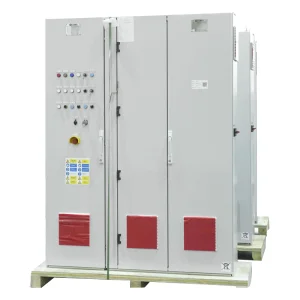
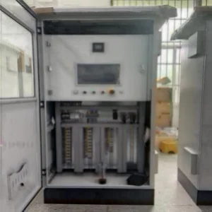
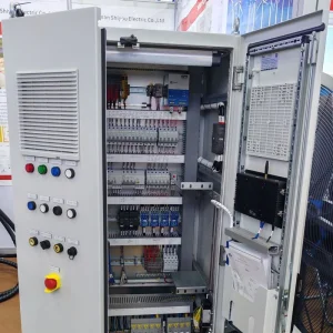
The ring main unit features a bus room, load switch or circuit breaker room, cable room, and an operating mechanism. It includes an interlocking mechanism, low-voltage control room, and measurement or metering circuits. Each compartment is divided by a steel plate to prevent failures from impacting adjacent rooms.
Positioned at the top of the cabinet, the bus room connects the main bus bars, which run horizontally through the switch cabinets for easy expansion.
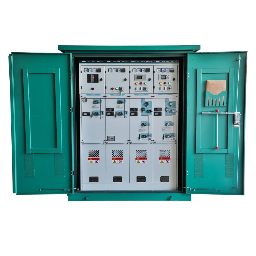
The load switch room houses a load switch with an epoxy resin shell filled with SF6 gas for arc extinguishing and insulation. Transparent plastic end covers allow observation of contact state. SF6 gas density meters with alarm contacts can be installed as per customer needs.
Located centrally, the circuit breaker room can be fitted with a vacuum or SF6 circuit breaker, designed to handle normal operations and special short-circuit conditions. It features a spring-operating mechanism for reliable action and extended service life.
| Project | Units | C Module | F Module | V Module | CB Module | ||
|---|---|---|---|---|---|---|---|
| Rated Voltage | KV | 12 | 12 | 12 | 12 | 12 | 12 |
| Rated Frequency | HZ | 50 | 50 | 50 | 50 | 50 | 50 |
| Power Frequency Withstand | KV | 42/48 | 42/48 | 42/48 | 42/48 | 42/48 | 42/48 |
| Lightning Shock Voltage | KV | 75/85 | 75/85 | 75/85 | 75/85 | 75/85 | 75/85 |
| Rated Current | A | 630 | infuse | 630 | - | 1250/630 | - |
| Mechanical Life | Times | 5000 | 3000 | 5000 | 2000 | 5000 | 2000 |
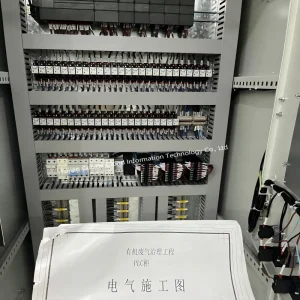
The cable room facilitates the connection of single-core or three-core cables with unshielded cable heads. It accommodates components like arresters and transformers. The standard-designed door offers viewing windows and interlocks, while the floor has a sealing cover and cable clamps.
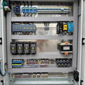
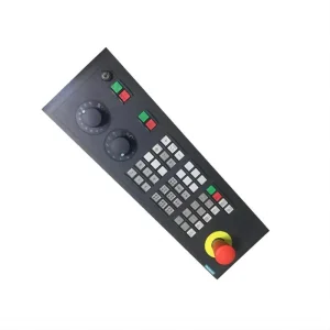
The interlocking low-pressure chamber serves as a control screen, equipped with a spring-operated mechanism, mechanical interlocking device, and auxiliary contacts. It supports emergency tripping mechanisms and electric devices.